


Views: 0 Author: Site Editor Publish Time: 2026-09-16 Origin: Site


Do uncontrolled cables cause your system to fail? In my years on the field, I have seen mechanical vibrations quietly tear apart heavy industrial electrical setups. What starts as a minor, almost invisible oscillation can rapidly transform into a catastrophic short circuit if left unchecked. Whether you are routing power through a bustling automotive plant, a commercial high-rise, or an exposed offshore platform, your electrical infrastructure is never truly static.
A properly engineered anchoring mechanism prevents costly abrasion and metal fatigue. It ensures continuous operation even in the harshest environments. In this detailed breakdown, drawn from direct engineering experience, you will learn how to secure your infrastructure safely, empirically, and permanently.
Vibration Control is Non-Negotiable: Unmanaged kinetic energy causes continuous jacket abrasion and severe internal metal fatigue. Using specialized dampening hardware absorbs these shocks before they reach the conductor.
Match the Hardware to the Architecture: Flat-surface restraints and rung-based anchors handle loads differently. Selecting the wrong clamping mechanism guarantees eventual structural failure.
Metallurgy Matters: Implementing lightweight, highly corrosion-resistant alloys—rather than standard plastics—provides a distinct operational advantage in heavy-industrial or offshore environments.
Precision Installation Preserves Strength: Over-tightening hardware crushes insulation (cold flow) and reduces internal wire tensile strength. Applying exact torque is the foundation of network stability.
Before jumping to solutions, we must understand the physical forces acting upon the routing infrastructure. Cables are constantly subjected to dynamic stresses that induce shifting, snaking, and high-frequency oscillation.
Mechanical vibrations typically originate from nearby machinery. Walk onto a stamping press floor or into a heavy compressor room, and you can literally feel the concrete humming. Heavy equipment—industrial motors, massive HVAC units, and backup generators—transmits kinetic energy through the building's structural framework directly into your trays. These low-frequency, continuous vibrations force the conductors to oscillate relentlessly against their metallic supports.
Furthermore, electromechanical forces present a highly volatile source of movement. During normal operation, alternating current (AC) creates minor magnetic fields causing subtle vibrations. However, during a short circuit, these magnetic fields multiply exponentially in milliseconds. The resulting Lorentz forces cause parallel phases to violently repel or attract each other. This sudden, severe mechanical stress can easily tear standard, under-specified hardware straight from the wall.
Environmental factors also play a critical role, particularly in exposed installations. High wind loads induce aerodynamic flutter. Meanwhile, thermal cycling—the daily transition between hot and cold—forces conductors to expand and contract, slowly shifting their position across the supports.
When you leave dynamic movement unmanaged, continuous micro-friction leads to severe jacket abrasion. As a heavy wire rubs against the hard edges of a perforated sheet or a steel rung, the outer polymer jacket slowly wears away. This chafing eventually exposes the inner shielding, creating a high-probability risk for ground faults or deadly arc flashes.
Looking beyond external wear, continuous vibration induces internal metal fatigue. Copper and aluminum conductors possess delicate crystalline structures. Unrelenting bending causes microscopic work-hardening. Over time, micro-cracks form within the metal strands, increasing electrical resistance, generating localized hot spots, and ultimately leading to complete system failure.
To mitigate these risks, engineers rely on specialized hardware. These components are not merely organizational accessories meant to keep a tray looking neat; they are critical safety devices engineered to maintain the physical integrity of the electrical network under extreme stress.
At its core, a restraint is a mechanical device designed to secure, guide, and support electrical lines along a designated routing path. By applying controlled radial pressure, the device holds the line firmly in place without deforming its internal geometry. Individual wires possess inherent flexibility, making them highly susceptible to kinetic forces. Anchors act as the stabilizing interface between the flexible line and the rigid support structure.
When installed at mathematically calculated intervals, these devices tie individual wires into a broader, unified cable fixing system. This integration transforms a vulnerable arrangement of loose wires into a rigid, organized, and structurally sound architecture. The hardware ensures the entire network moves as a single cohesive unit, drastically reducing localized stress points.
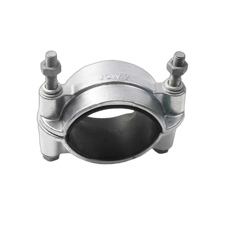
In environments characterized by heavy rotating machinery or extreme wind loads, standard rigid metal fasteners simply will not survive. To actively dampen kinetic energy and protect the jacket from continuous dynamic stress, a specialized vibration resistant cable clamp is strictly required.
The effectiveness of shock-absorbing hardware lies entirely in its internal construction. These components typically feature a heavy-duty outer shell lined with engineered elastomeric cushions. Common dampening materials include Ethylene Propylene Diene Monomer (EPDM) rubber or Low-Smoke Zero-Halogen (LSZH) silicone inserts.
Specifically, when kinetic energy travels from the support structure into the fastener, these viscoelastic liners compress slightly. This microscopic compression absorbs the shockwaves, converting kinetic energy into minute amounts of thermal energy rather than transferring the destructive force into the polymer jacket. The pliable liners also increase the coefficient of friction, ensuring a secure grip without requiring excessive, damaging mechanical clamping force.
Selecting the appropriate hardware requires a precise understanding of the underlying support structure. While they may appear similar to the untrained eye, flat-surface restraints and rung-based anchors serve entirely different structural purposes. Applying the wrong component leads to inadequate load distribution and eventual slippage.
A cable tray clamp is explicitly designed for solid-bottom or perforated sheet metal routing paths. Here, the wire rests on a continuous flat surface. The primary function of the fastener is to prevent lateral shifting and longitudinal migration caused by thermal expansion. Because the flat sheet provides continuous vertical support, these fasteners feature a wide, low-profile base that distributes compressive force evenly across the jacket.
In contrast, rung-based architectures consist of two longitudinal side rails connected by transverse metal rungs. This open design is favored for heavy, high-voltage power feeders to maximize airflow and heat dissipation. To secure infrastructure here, a cable ladder clamp must be engineered to securely grip specific profiles (C-shaped, unistrut, or tubular).
Unlike flat installations, lines on a ladder are only supported at intervals. Therefore, the fastener must withstand significant point-loads, prevent sagging, and hold immense weight in vertical drops. It must feature a robust locking mechanism that wraps entirely around the rung.
Feature | Flat-Surface (Tray) Restraints | Rung-Based (Ladder) Anchors |
|---|---|---|
Primary Structural Support | Continuous flat or perforated sheet | Intermittent transverse rungs |
Main Mechanical Function | Prevents lateral shift & thermal snaking | Handles high point-loads & vertical drops |
Base Design | Wide, low-profile footprint | Wraparound locking mechanism (Unistrut/C-profile) |
Typical Application | Control lines, data routing, low/med voltage | High-voltage feeders, heavy industrial power |
The physical material of a restraint dictates its mechanical limits and lifespan. While industrial plastics and carbon steel are common, specifying an aluminum cable support occupies a critical middle ground, offering specific metallurgical advantages for dynamic environments.
Aluminum alloys (particularly the 5000 and 6000 series) exhibit an exceptional strength-to-weight ratio. In environments subject to continuous mechanical vibration, excessive dead weight on the routing system exacerbates structural fatigue. Utilizing lightweight metals alters the resonant frequency of the installation, effectively mitigating the amplification of vibrations. For example, high-grade aluminum cleats can securely hold outer diameters ranging from 15mm up to 150mm, easily withstanding short-circuit fault currents up to 130kA without adding unnecessary bulk to the tray.
Beyond weight advantages, aluminum naturally forms a dense oxide layer upon atmospheric exposure. This passivation provides inherent corrosion resistance without secondary coatings (like galvanization) that chip away under continuous vibration. Furthermore, aluminum is entirely non-magnetic, preventing the induction of eddy currents and localized heating that plagues standard carbon steel in high-voltage AC applications.
Thermoplastic polymers, while inexpensive, are highly susceptible to mechanical creep and fatigue cracking under continuous dynamic stress. Prolonged UV exposure rapidly degrades polymer chains, rendering them dangerously brittle. Aluminum provides a pragmatic engineering compromise: it avoids the brittleness of plastics while offering immense tensile strength at a fraction of the weight of stainless steel.
As industrial facilities modernize, the demands placed on electrical routing systems have shifted dramatically. A prominent trend in the current engineering landscape is the move toward predictive maintenance and hyper-resilient infrastructure. With the rapid expansion of hyperscale data centers and renewable energy projects—such as offshore wind farms—systems are now designed to handle unprecedented short-circuit fault levels.
This massive increase in potential fault energy is driving the industry away from basic, rigid plastic fasteners. The market is shifting aggressively toward advanced viscoelastic dampening technologies and aerospace-grade metal alloys. Regulatory bodies are enforcing stricter compliance (such as the IEC 61914 standards) regarding electromechanical restraint. Consequently, facility managers are increasingly retrofitting legacy systems with shock-absorbing, high-tensile hardware to prevent catastrophic downtime and ensure total safety compliance.
Even the most meticulously engineered hardware will fail if installed incorrectly. Field installation practices directly dictate the long-term viability of your electrical network. The most critical factor is determining the correct mathematical spacing between anchor points. If anchors are spaced too far apart during a short circuit, parallel phases will whip violently, shattering insulation and initiating an arc flash. Engineers must calculate the peak fault current (kA) and wire diameter to determine the maximum allowable distance between supports.
In addition, installers must apply the correct torque. Every industrial-grade component is supplied with a specific torque rating determined through rigorous laboratory testing. You cannot rely on muscle memory or aggressive impact drivers. Under-torquing leaves the line loose, inviting vibrational chafing.
Conversely, a prevalent field error is over-tightening, which physically crushes the polymer insulation. This "cold flow" forces the insulation to migrate away from the pressure point, dangerously reducing the dielectric barrier. Excessive radial compression also deforms the internal conductors, altering their precise geometric stranding. This creates localized bottlenecks for the current, introduces stress concentrations, and significantly reduces tensile strength. Achieving a secure hold without crushing the line requires strict adherence to empirical torque data and properly engineered elastomeric liners.
Controlling kinetic energy and dynamic movement is vital for the safety, efficiency, and longevity of any industrial electrical system. Unmanaged vibrations and electromechanical forces cause compounding damage over time, leading to dangerous faults and expensive operational downtime. By selecting the right hardware—tailored specifically to your flat-sheet or rung-based architecture—you secure the infrastructure against catastrophic failure.
Prioritize appropriate materials like aluminum for harsh environments and adhere strictly to calculated installation practices to ensure a resilient network. Don't leave your infrastructure to chance. Evaluate your current routing setup today, and explore professional, field-tested solutions at Supercleat to maintain optimal operational performance and safety compliance.
A vibration resistant device typically features shock-absorbing inner liners, such as elastomeric polymers, EPDM, or silicone cushions. These pliable materials compress to absorb kinetic energy, while a secure mechanical locking system prevents the hardware from vibrating loose under continuous shaking.
Spacing is not a guessing game; it depends entirely on the peak fault current (kA) of your system and the outer diameter of the conductor. In high-vibration or high-fault areas, spacing is often reduced to every 300mm to 600mm. Always consult IEC 61914 testing data provided by the manufacturer to calculate the precise intervals for your specific load.
If installed incorrectly, yes. Over-tightening the hardware can crush the protective polymer jacket and permanently deform the internal metal conductors (a phenomenon known as cold flow). This introduces stress concentrations that reduce the tensile strength of the wire and compromise its electrical integrity.
During a short circuit, massive electromagnetic Lorentz forces cause parallel cables to violently repel or attract one another in milliseconds. On an open ladder, if the restraints are inadequate, this explosive kinetic energy can snap the cables off the rungs, causing them to whip dangerously. This is why heavy-duty, wraparound ladder anchors are required for high-voltage feeders.
Generally, no. Flat-surface fasteners are engineered with wide bases to attach to solid or perforated sheet metal. Rung-based anchors are specifically designed with wraparound mechanisms to securely grip structural profiles (like Unistrut), allowing them to handle the higher point-loads and vertical drops associated with open architectures.
Metals like aluminum provide superior mechanical tensile strength, excellent heat dissipation, and total resistance to UV degradation compared to plastics. Plastics suffer from mechanical creep and become brittle over time, making metal alloys far more reliable for heavy-duty applications subjected to continuous dynamic stress.
Industry best practices dictate inspecting your support network annually. Furthermore, immediate visual and mechanical inspections are mandatory following any major short-circuit event, severe weather exposure, or significant changes to the surrounding mechanical environment to ensure no components have vibrated loose.


