


Views: 0 Author: Site Editor Publish Time: 2026-09-30 Origin: Site


Did you know an unconstrained electrical cable can whip with the force of several tons during a short circuit? It happens in milliseconds. As engineers, we know that choosing the correct securing mechanism prevents catastrophic infrastructure damage. But the decision goes far beyond simply measuring wire diameter. It depends entirely on your specific setup.
On the job site, guesswork leads to disaster. You cannot rely on zip ties or uncertified metal banding when dealing with high fault currents. Let's break down how to evaluate your infrastructure's physical footprint, thermal limits, and electromagnetic constraints to match your layout with the exact restraining device required.
Layout Dictates Cleat Type: The physical and electromagnetic requirements of your electrical system demand a precise match. You must choose between a single, trefoil, or quad design based on your exact geometric configuration.
Trefoil is Standard for 3-Phase: Triangular formations are the industry benchmark for medium and high voltage (MV/HV) systems. This grouping neutralizes electromagnetic fields and prevents induced heating in nearby structures.
Flat Formations Maximize Cooling: Securing lines side-by-side provides superior heat dissipation, allowing for higher ampacity. However, this method consumes significantly more space on the routing pathway.
Compliance is Non-Negotiable: Safety relies on empirical data. All selections must be calculated against peak short-circuit fault currents and strictly adhere to IEC 61914 standards.
A securing bracket or clamp is a vital safety device engineered to anchor electrical lines to ladder racks, trays, and structural mounts. While they provide essential power cable support against the constant downward pull of gravity—especially in deep vertical shafts—their primary function is far more critical. During a short-circuit fault, electrical systems experience massive surges in current. This sudden spike generates extreme electromagnetic forces. Parallel conductors instantly and violently repel one another.
Without proper restraint, these lines thrash with devastating force. We've seen unrestrained cables destroy adjacent infrastructure, tear end terminations from their lugs, and pose severe lethal risks to personnel.
However, selecting the right restraint is not a one-size-fits-all endeavor. The decision is fundamentally driven by the geometric layout of the lines. In industrial and utility-scale electrical engineering, routing is never random. How you arrange your conductors directly impacts the system's operational safety and efficiency.
Specifically, the arrangement affects three primary engineering variables:
Electromagnetic Field (EMF) Cancellation: Different layouts alter how magnetic fields interact. Poor arrangements induce eddy currents in adjacent metal structures. This leads to dangerous localized heating and severe fire risks.
Heat Dissipation and Ampacity: Conductors generate heat based on electrical resistance. Grouping them tightly restricts airflow, lowering the system's current-carrying capacity (ampacity). Spacing them out improves natural convection cooling.
Physical Footprint: The available width on a ladder or trench dictates how circuits can be physically routed through congested industrial bottlenecks.
A flat formation occurs when individual single-core lines are laid out side-by-side in a horizontal or vertical plane. In this configuration, each conductor is secured independently using a single cable cleat. This arrangement is standard in low voltage (LV) alternating current systems, direct current (DC) power lines, and specific high-capacity installations where thermal management is the primary engineering constraint.
In a flat layout, these brackets are bolted directly to the underlying support structure. They encapsulate one line at a time to provide rigid mechanical retention. Depending on your short-circuit calculations, you may need to space these clamps at tight, regular intervals. This prevents the conductors from bowing or snapping under electromechanical lateral shear stress.
Why choose a flat layout? Because the lines are not bundled together, maximum surface area is exposed to ambient air. This allows for excellent natural convection cooling. According to IEC 60287 standards, flat formations with adequate spacing (typically one diameter apart) suffer from minimal thermal derating. This maximizes the ampacity of your copper or aluminum conductors. Furthermore, tracing a specific phase or identifying a localized insulation fault is significantly easier when lines are visibly separated.
In contrast, the major drawback is the massive space requirement. Laying lines side-by-side consumes a vast amount of width on a tray. In highly congested chemical plants or offshore platforms, this real estate simply doesn't exist. Additionally, laying three phases (L1, L2, L3) flat means the magnetic fields do not naturally cancel each other out. If not properly spaced and transposed, you will face unbalanced induced voltages and the heating of nearby ferrous metals.
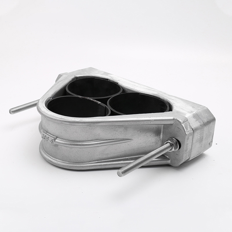
The term "trefoil" refers to a specific geometric arrangement where three single-core lines are bundled together in a triangular pattern. Think of a three-leaf clover. This compact configuration is universally recognized as the gold standard for medium voltage (MV) and high voltage (HV) three-phase AC power distribution.
In a three-phase electrical system, the alternating currents are offset by 120 degrees. When you group these three conductors tightly in a symmetrical triangle, the vector sum of their electromagnetic fields essentially cancels out to near zero. This physical phenomenon is critical. If these powerful magnetic fields were not neutralized, they would induce eddy currents in surrounding steel trays or structural beams. Over time, this induced current causes rapid, localized heating, degrading insulation and weakening supports.
Securing this triangular bundle requires highly specialized hardware. A trefoil cable cleat is engineered to encapsulate all three lines simultaneously. During a short-circuit fault, the immense electromagnetic forces cause the three phases to violently repel each other outward. The clamp acts as a high-tensile structural belt. It contains this explosive outward radial force and keeps the trefoil geometry perfectly intact.
From a product specification standpoint, modern heavy-duty aluminum trefoil cleats are built for extreme environments. For instance, high-grade aluminum alloy models are often epoxy-coated to resist corrosion in harsh offshore conditions. They are designed to accommodate specific Outer Diameter (OD) ranges—such as 23-36mm, 33-47mm, or even up to 115mm for massive industrial feeds. More importantly, top-tier aluminum trefoils are rigorously tested to withstand peak short-circuit currents exceeding 130kA, ensuring your infrastructure survives a catastrophic fault.
Bundling three phases into a single triangular profile drastically reduces the required width on a ladder. This allows you to run more circuits in a confined space. However, thermodynamics play a role here. Because the three lines are in direct physical contact, they heat each other up. The inner surfaces of the bundle have zero airflow. As a result, engineers must apply strict derating factors to the system's current-carrying capacity.
A quad formation is a tightly packed square bundle of four individual conductors. While less common than flat or triangular arrangements, quad layouts solve highly specific engineering challenges in complex electrical distribution networks.
We primarily deploy a quad cable cleat in two distinct scenarios. First, in three-phase systems where unbalanced loads are anticipated, a dedicated neutral line is required alongside the three power phases. Bundling all four together ensures the neutral remains in close proximity to the phases, maintaining predictable impedance. Second, for complex control systems or low-voltage power distribution, engineers bundle multiple circuits purely to maximize space efficiency on routing pathways.
The primary advantage of a quad formation is its exceptional space efficiency. By stacking four lines into a square profile, you can route complex systems through incredibly tight bottlenecks. But this comes at a thermodynamic cost. A quad bundle traps more heat than any other formation. The core of the bundle experiences significant temperature rise, requiring aggressive derating of the ampacity. Moreover, the short-circuit stress distribution in a square bundle is asymmetrical. These specific clamps must be manufactured from exceptionally rigid materials to prevent deformation during a fault.
When evaluating electrical system designs, selecting the appropriate securing mechanism is an engineering decision, not a purchasing afterthought. To make an informed choice, you must objectively compare how different configurations perform across critical metrics.
Evaluation Metric | Single (Flat Formation) | Trefoil (Triangular Formation) | Quad (Square/Bundle Formation) |
|---|---|---|---|
Space Efficiency | Poor. Lines are laid side-by-side, consuming significant horizontal width on the ladder or tray. | Great. Bundling three phases into a tight triangle drastically reduces the required tray width. | Best. Consolidates four lines (often three phases plus neutral) into the smallest possible cross-sectional footprint. |
Heat Dissipation | Best. Maximum surface area is exposed to ambient air, minimizing ampacity derating factors. | Moderate. Lines are in direct contact with one another, leading to localized heat build-up. | Lowest. The bundled nature traps heat in the center of the configuration, requiring strict thermal derating. |
Electromagnetic Balance | Variable. Requires precise physical spacing to minimize induced currents; imbalances can cause interference. | Best. The symmetrical triangular arrangement naturally cancels out electromagnetic fields in 3-phase systems. | Moderate to Good. Effective when bundling a balanced three-phase system with a precisely sized neutral conductor. |
Short Circuit Handling | High. Forces push lines apart laterally; brackets must withstand immense horizontal shear stress. | Exceptional. Absorbs outward radial forces uniformly, containing the explosive repulsion of the three phases. | Complex. Fault forces are distributed unevenly across the four lines; requires highly specialized engineering. |
Understanding this matrix is the first step in mitigating risk. While a flat layout offers superior thermal performance, densely packed industrial plants often cannot accommodate them. This makes trefoil or quad configurations mandatory despite their thermal drawbacks.
The landscape of industrial electrical infrastructure is rapidly evolving. With the aggressive global push toward renewable energy—particularly offshore wind farms, hyperscale data centers, and large-scale solar arrays—grid modernization is driving system voltages and potential short-circuit fault levels higher than ever before.
Today, fault currents in utility-scale projects frequently exceed 100kA to 130kA. Consequently, the industry is seeing a massive shift away from traditional, low-spec securing methods. Project managers are now mandating highly engineered, rigorously tested restraint systems. Because modern renewable grids utilize massive MV/HV three-phase systems to transmit power over long distances, the demand for ultra-high-strength aluminum trefoil configurations has skyrocketed.
Furthermore, safety regulations in confined spaces—such as underground transit systems and marine vessels—are forcing a transition in material science. There is a growing trend toward advanced Low Smoke Zero Halogen (LSZH) polymeric materials and epoxy-coated aluminum alloys. These materials offer the tensile strength required to survive a fault without the risk of galvanic corrosion or toxic smoke emissions during a fire event.
Once your cable arrangement is finalized, selecting the specific hardware involves rigorous mathematical calculation. A catastrophic short circuit generates tons of electromechanical force in milliseconds. You cannot choose a product based on visual preference or price alone. Here is how you evaluate the hardware.
IEC 61914 Standards: Compliance with international safety standards is non-negotiable. The IEC 61914 standard is the globally recognized benchmark for testing and certifying these critical components. It outlines specific testing protocols for electromechanical force resistance, lateral and axial load bearing, impact resistance, and temperature tolerance. Always ensure the product has been independently tested to withstand your design's specific fault conditions.
Calculating Short-Circuit Current: The primary function of these devices is to prevent violent whipping during a fault. Therefore, the peak short-circuit fault current is your most vital metric. Because parallel conductors carrying current in opposite directions repel each other, a magnetic spike translates into explosive mechanical force. The mechanical strength of your chosen restraint must exceed this calculated peak force. Otherwise, the polymer will shatter, or the metal will tear.
Outer Diameter (OD) Matching: Precision is critical. Securing mechanisms are engineered with highly specific clamping ranges (e.g., 24-36mm or 33-47mm). The OD of your line must fall squarely within the manufacturer’s specified range. If the device is too large, the line will slip during vertical runs. If it is too small, tightening the fasteners will crush the outer sheath and internal insulation, leading to partial discharge and eventual electrical breakdown.
Material Selection: The operational environment dictates the material composition. Stainless Steel (316L) and epoxy-coated Aluminum Alloy offer the highest mechanical strength and unparalleled resistance to corrosion. This makes them mandatory for offshore oil rigs and heavy chemical processing plants. High-grade polymers or glass-filled nylon are ideal for standard industrial applications, eliminating the risk of eddy currents.
Even the most highly specified, IEC-certified components will fail if installed incorrectly. Proper installation requires strict adherence to engineering calculations and a deep understanding of dynamic forces.
One of the most frequent installation errors is improper spacing. There is no universal standard distance. Instead, the spacing must be mathematically calculated based on the peak short-circuit current, the conductor diameter, and the tested mechanical strength of the clamp. If spaced too far apart, the electromechanical forces will overcome the rigidity of the copper. The lines will thrash between the securing points. You must utilize short-circuit calculators to determine the exact optimal distance.
Installing single-core Aluminum Wire Armour (AWA) lines introduces a unique set of engineering challenges, particularly in a trefoil configuration. Because AWA systems carry high alternating currents, they generate significant magnetic fields. A critical pitfall is using standard ferromagnetic (mild steel) brackets to secure them. The magnetic field induces circulating eddy currents within any closed magnetic loop, leading to severe localized heating that melts insulation. Always use non-magnetic materials—such as aluminum, polymer, or specific grades of stainless steel—when securing single-core AWA setups.
Finally, consider your routing. The dynamic forces acting on a system change significantly when navigating bends or vertical runs. When turning corners, radial loads are introduced. During a short circuit, lines attempt to straighten out, exerting immense pressure on the inside or outside of the bend. To counteract this, reduce the spacing between securing devices around corners. Vertical runs introduce the constant downward axial load of gravity, requiring specialized anchor grips or friction-enhancing liners to prevent slipping.
Choosing the correct securing hardware depends entirely on your layout. Every electrical system has unique physical, thermal, and spatial requirements that dictate whether a flat, triangular, or square configuration is required. From maximizing ampacity with single flat layouts to neutralizing magnetic fields with aluminum trefoil designs, your engineering choices directly impact site safety.
Always prioritize safety by adhering strictly to IEC 61914 standards. Never underestimate the destructive power of a short circuit. The forces generated in a fraction of a second can tear apart steel infrastructure and cause fatal injuries. By using precise calculations for your specific arrangement and selecting the appropriate materials, you ensure the long-term integrity of your electrical network. Ready to secure your infrastructure with certified, heavy-duty solutions? Evaluate your OD ranges and fault currents, and choose the precise engineered restraint for your project at Supercleat today.
No, this is a highly dangerous practice. During a short-circuit event in a three-phase system, the electromagnetic forces cause the three individual phases to violently repel one another. A trefoil device is specifically engineered to wrap around the entire three-cable bundle, containing that outward explosive force and maintaining the critical triangular formation. Using three separate securing devices cannot contain this collective radial force, leading to mechanical failure and severe damage to the tray and surrounding infrastructure.
There is no universal standard distance. The required spacing is a highly specific engineering calculation based on three primary variables: the outer diameter of the conductor, the calculated peak short-circuit current of the electrical system, and the certified mechanical strength of the chosen device. Depending on these factors, the spacing typically ranges anywhere from 300mm for high-fault systems to 1200mm for low-risk installations. Always rely on short-circuit calculations rather than arbitrary estimates.
Yes, restraints are absolutely necessary even in underground concrete trenches. While the trench provides physical isolation from personnel, the physics of a short circuit remain exactly the same. Unrestrained lines in a trench will thrash violently during a fault. This movement can severely abrade the outer jacket against the rough trench walls, shatter the concrete routing, and rip the copper out of their end terminations. Securing them ensures the mechanical integrity of the entire circuit.
Precision is critical for safe operation. If the device is too loose, it fails to provide adequate axial restraint, allowing heavy lines to slip downward during vertical runs or thrash uncontrollably during a short-circuit fault. If the device is too tight, the mechanical pressure will crush the outer sheath and deform the internal insulation. Over time, this deformation leads to localized hotspots, partial discharge, and eventual catastrophic electrical breakdown.
Calculating the short-circuit force requires knowing the peak fault current (Ip) of your system and the center-to-center distance between the conductors. Using the formula provided in IEC 61914, the maximum electromechanical force (F) is proportional to the square of the peak short-circuit current and inversely proportional to the spacing between the conductors. Once you calculate this force in Newtons per meter (N/m), you compare it against the certified loop strength of the cleat to determine the maximum safe installation spacing.
Metallic cleats, typically made from 316L stainless steel or epoxy-coated aluminum alloy, offer superior mechanical strength and are designed for extreme fault currents, harsh industrial environments, and offshore applications. Non-metallic cleats, made from high-grade polymers or glass-filled nylon, are corrosion-resistant, naturally prevent eddy currents, and are highly cost-effective for standard industrial or commercial installations with lower short-circuit fault risks.


