


Views: 0 Author: Site Editor Publish Time: 2026-09-25 Origin: Site


How tight should a cable fastener really be?
Too loose, and your heavy wiring inevitably slips under its own weight. Too tight, and you risk crushing the vital protective jacket. Achieving this delicate balance is a daily, critical dilemma for field engineers and electricians. We've all been there—standing on a lift, wrench in hand, wondering if one more turn will secure the line or compromise a multi-thousand-dollar installation.
In this guide, we dive deep into the engineering behind clamping pressure. We will demystify exact torque rules, explore material choices, and outline actionable installation practices. By understanding the mechanical limits of modern wiring, you can secure your infrastructure without sacrificing system longevity.
Torque is Everything: Relying on "feel" or muscle memory is a recipe for disaster. Always follow manufacturer torque specifications for the perfect grip.
Sheath Integrity Equals Safety: Damaging the outer jacket leads to moisture ingress, electrical hazards, and catastrophic system failures.
Material Matters: The choice between stainless steel and advanced polymers depends on environmental corrosivity and grounding requirements.
Dynamic Load Defense: Heavy industrial applications demand specialized cleats tested to withstand violent short-circuit fault currents.
To truly grasp why clamping pressure is a vital metric, you must look at the internal architecture of the wiring. A high-capacity power line isn't just a solid chunk of copper. It is a carefully engineered assembly of distinct layers, each serving a highly specific purpose.
At the core lies the conductor, carrying the current. Surrounding this is the insulation layer (typically XLPE, EPR, or PVC) designed to prevent electrical leakage. Next comes the metallic shielding, which confines the electric field and provides a safe path for fault currents. Wrapping everything together is the outer sheath.
This outer jacket acts as the absolute first line of defense. It blocks moisture, resists chemical exposure, deflects UV radiation, and absorbs mechanical impacts. Consequently, ensuring proper cable sheath protection is not a cosmetic concern. It is a fundamental safety requirement.
The cost of compromise is exceptionally high. If a fastener bites into the plastic jacket, it creates a localized stress point. Over time, this intense pressure transfers to the underlying insulation layer, causing it to thin out and altering the dielectric strength of the line. The result? Localized heating, electrical arcing, and ultimately, catastrophic failure. Replacing a damaged high-voltage line due to a botched installation results in massive downtime and staggering labor costs.
Looking at the current trajectory of the electrical sector, we are witnessing a massive scale-up in renewable energy grids, offshore wind farms, and hyperscale data centers. This shift brings significantly higher transmission voltages and unprecedented load demands. Consequently, the potential short-circuit fault currents in these modern facilities are reaching extreme levels.
Field engineers are realizing that legacy fastening methods simply cannot handle these dynamic electromechanical forces. During a short circuit, massive current surges generate Lorentz forces, causing adjacent wires to violently repel each other. They can whip around with enough kinetic energy to destroy surrounding infrastructure. The industry is rapidly moving away from basic brackets toward precision-engineered cleats that guarantee structural integrity during these violent fault events.
In commercial electrical systems, securing these heavy lines safely requires exact hardware. For general routing in low-stress environments, a standard bracket is often sufficient. They support the static weight of the wiring along walls or trays, keeping the installation organized.
In contrast, high-voltage lines in heavy industrial environments require specialized hardware. Engineers must specify a single cable cleat designed explicitly to withstand immense dynamic loads. These devices undergo rigorous international testing (such as IEC 61914) to guarantee they can contain the explosive force of a fault without rupturing the outer jacket.
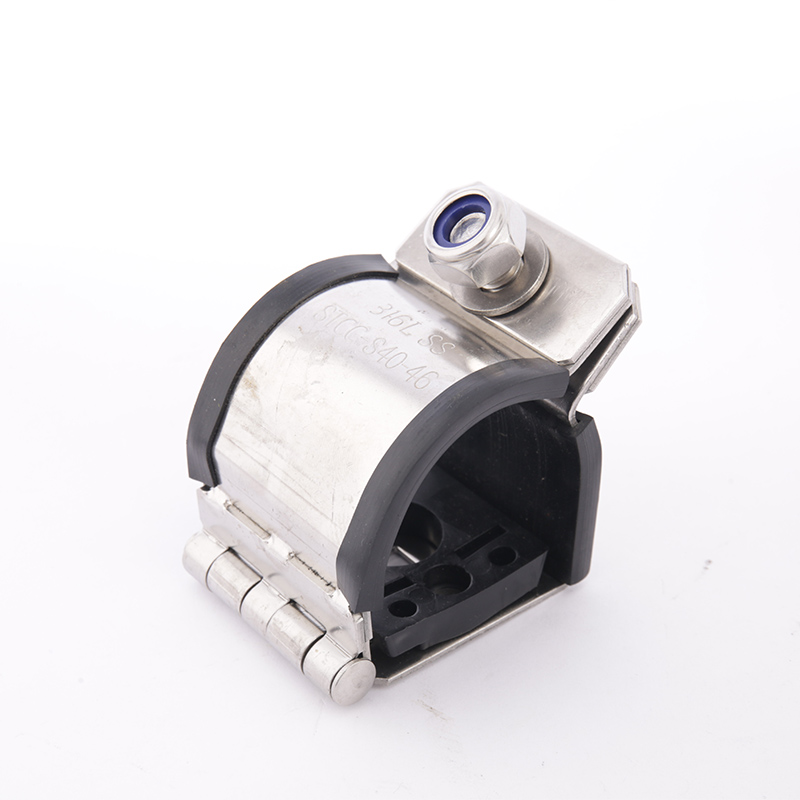
The most frequent question on the job site is exactly how tight the hardware should be. Relying on "hand-tightness" or the arbitrary "feel" of a wrench is a primary cause of premature failure. Achieving the perfect grip requires understanding the physical limits of the polymers and metals involved.
Picture this scenario: you are tightening a bolt on a thick XLPE-insulated line. Without a torque wrench, you rely on muscle memory. Suddenly, the jacket bulges slightly at the edges of the bracket. You've gone too far. When over-tightened, the hardware compresses both the outer jacket and the internal insulation, altering the concentricity of the wire. This creates dangerous "hot spots" where electrical resistance artificially spikes.
Furthermore, polymeric sheaths are highly susceptible to "cold flow" or "creep." Under constant, crushing pressure, the plastic material slowly deforms and flows away from the stress point. Even if the installation looks flawless on day one, cold flow can expose the internal shielding months later.
Conversely, under-tightening presents its own severe risks. A loose grip fails to secure the weight against gravity. More importantly, it allows for micro-movements caused by ambient vibration and natural thermal expansion. Continuous friction chafes and wears away the outer barrier.
The golden rule is straightforward: stop guessing and utilize a calibrated torque wrench. Manufacturers engineer their hardware based on extensive destructive testing. Adhering to the specific Newton-meter (Nm) ratings guarantees maximum grip strength while maintaining a wide safety margin.
Installation State | Physical Impact on Cable | Long-Term System Risks |
|---|---|---|
Over-Tightened (Crushed) | Jacket deformation, insulation thinning, cold flow (creep). | Hot spots, arc faults, compromised dielectric strength, water ingress. |
Under-Tightened (Loose) | Micro-movements, vibration chafing, slipping under gravity. | Jacket abrasion, loss of short-circuit containment, mechanical fatigue. |
Optimal (Torque to Spec) | Even pressure distribution, accommodates thermal expansion. | Maximum lifespan, guaranteed short-circuit protection, code compliance. |
The material composition of the fastener directly dictates its mechanical performance and interaction with the broader electrical grid. Electrical codes closely regulate these choices based on the installation environment.
Metallic hardware, such as 304 or 316L stainless steel, is heavily favored in offshore, petrochemical, and heavy industrial sectors. They offer exceptional tensile strength, extreme temperature tolerance (often rated from -50°C to +60°C or higher), and high fire resistance. However, the rigid nature of metal means it can easily slice into a softer jacket if over-torqued. To mitigate this, premium metallic hardware features integrated elastomeric cushion liners. Additionally, because they are conductive, these parts often require strict grounding to prevent them from becoming energized during a fault.
For many commercial applications, non-metallic materials are the preferred choice. Heavy-duty nylons and advanced polymers naturally offer better conformance to a cylindrical shape. They are inherently non-conductive, eliminating the need for complex grounding loops, and are immune to galvanic corrosion. The primary drawback is that standard plastics degrade when exposed to continuous high heat or UV radiation, making UV-stabilized formulations critical for outdoor use.
Proper installation technique is just as critical as selecting the correct hardware. Precision can be difficult in the field, which is why following a standardized procedure ensures consistency and safety across the entire facility.
Step 1: Preparation and Sizing
Never rely blindly on the nominal size printed on the drum, as manufacturing tolerances fluctuate. Use a digital caliper to accurately measure the actual outer diameter (OD) of the wire at multiple points. Select an electrical cable support whose specified clamping range safely accommodates this exact measurement.
Step 2: Positioning
Consult the project engineering guidelines for correct spacing intervals. Hardware must be spaced appropriately along vertical or horizontal runs to distribute the massive weight evenly. Vertical runs inherently require much closer spacing to combat the concentrated forces of gravity.
Step 3: Fastening and Torquing
Ensure the wire is seated perfectly in the center of the saddle. If the bracket utilizes two bolts, do not tighten one side completely before moving to the other. Instead, alternate sides—tightening just a few threads at a time. This alternating method prevents the hardware from tilting and pinching the jacket. Finally, use a calibrated torque wrench to apply the exact manufacturer specification.
Step 4: The Push/Pull Test
Once torqued to spec, perform a gentle manual push/pull test. Grip the line near the fixture and apply moderate lateral and vertical force. It should remain entirely immobilized. If movement occurs, verify the OD measurement immediately. Do not simply over-torque the bolts to compensate for a sizing error.
Analyzing field failures often reveals a frustrating pattern of entirely preventable installation errors. Avoiding these common pitfalls is essential for long-term system reliability.
Using the wrong size is the most frequent offense. Forcing a slightly undersized cable fixing clamp onto a larger line causes immediate point-loading. The rigid edges dig directly into the plastic. Conversely, using an oversized bracket provides zero mechanical grip, rendering the installation useless against vibration.
Another major oversight is ignoring thermal expansion. High-capacity lines generate significant heat when carrying heavy loads, causing internal conductors and external jackets to expand. A properly specified fixture accommodates these minute dimensional changes. If a technician over-tightens the hardware while the wire is cold, subsequent thermal expansion presses violently against the rigid metal, leading to eventual rupture.
Finally, substituting standard nylon zip ties for structural hardware is a dangerous code violation. Zip ties possess low tensile strength, feature narrow profiles that act like blades under pressure, and have zero capacity to withstand the dynamic loads of industrial environments.
Securing heavy infrastructure effectively requires partnering with manufacturers who prioritize rigorous engineering over basic mass production. When evaluating procurement options, facility managers should demand transparent technical data. Look for third-party testing certifications (like IEC 61914), precise OD range charts, and explicit torque guidelines.
A premium manufacturer understands that the hardware must act as a protective cradle, not just a vice. High-quality solutions feature engineered geometries, such as chamfered edges or integrated elastomeric liners, which actively prevent rigid parts from biting into the jacket.
For demanding environments where short-circuit protection is paramount, utilizing a specialized power cable clamp ensures the system withstands violent electromechanical forces while maintaining 100% integrity. Investing in properly engineered hardware at the start of a project eliminates the hidden, long-term costs of jacket degradation and crippling system downtime. If you are upgrading your facility or planning a new installation, ensure your hardware meets the highest international standards by exploring the engineered solutions available at Supercleat.
Yes, if the hardware is severely over-tightened. When excessive force crushes the outer sheath, that pressure transfers directly to the internal insulation and the conductive core. This compression can physically deform the copper or aluminum strands, reducing their cross-sectional area. A reduced cross-section artificially increases electrical resistance at that specific point, leading to dangerous localized heat build-up.
While not strictly mandatory for every light-duty application, utilizing a rubber or polymeric liner inside a metallic fixture is highly recommended by engineering professionals. A liner acts as a cushion, preventing rigid metallic edges from slicing into the softer plastic jacket. It also absorbs ambient mechanical vibrations, preventing chafing over time, and accommodates slight thermal expansion.
The distinction lies primarily in their engineering purpose and load-bearing capabilities. A standard fixture is designed for general routing and static weight support in low-stress environments. Conversely, a cleat is a highly specialized, heavy-duty safety device. Cleats are specifically engineered and independently destruct-tested to withstand the massive, instantaneous electromechanical forces generated during a short-circuit fault.
In standard commercial environments, a visual inspection should be conducted at least once a year. However, in harsh industrial settings, areas with high vibration, or outdoor installations exposed to extreme weather, inspections should occur semi-annually. Look for visible slippage, corrosion on metallic hardware, UV embrittlement on plastics, and any signs of indentation on the jacket.
There is no single universal torque setting. The correct torque depends entirely on the bolt size, the material of the cleat, and the outer diameter of the wire. Typically, manufacturer specifications range from 3 Nm to 15 Nm. Always consult the specific installation manual provided by the manufacturer, and always use a calibrated torque wrench rather than relying on feel.
Never rely on the nominal size listed on the wire's spec sheet, as manufacturing tolerances can vary by several millimeters. Use a digital caliper to measure the actual overall diameter (OD) of the physical wire on-site. Select a cleat where your measured OD falls comfortably within the middle of the cleat's specified clamping range, rather than at the absolute minimum or maximum limit.


